Hello! This is a project I made for my Physics 2E Honors
class. For the spring honors project, we were given several options—writing a
research paper, creating a poster board, making a video on something related to
the field of electronics, or building a prototype. I enjoy hands-on learning,
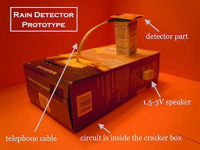
so I chose to build something. Here is the rain detector I created!
Due to a lack of laboratory supplies and the fact that this
is a prototype, the circuit sits inside a cracker box, and the detector sits
atop a mini cardboard box. Realistically, the circuit would be shrunk down and
nestled in a durable container, and the telephone cable would be longer to
allow the detector portion to be placed on a rooftop. But the cracker box
served me well.
These two videos illustrate the rain detector in action.
Since replicating a rainstorm would have been a bit messy, “rain drops” were dispensed from a dropper to
simulate the same situation.
And here is a close-up of the part of the circuit that
actually comes in contact with the raindrops. I did not have access to copper
wire, so with a little time and effort, I took the thin copper wires from a
telephone cable and twisted them together. There are two separate copper wires running across the circuit board. When a rain drop bridges two adjacent wires, the circuit makes a beeping sound. The beep speed can be adjusted by changing the value of the capacitors in the circuit (on breadboard, inside the cracker box).
Here is an aerial view of the rain detector.
Here is a side view. The speaker is sticking out of the
cracker box, right where the “Nutrition Facts” are printed.
Here is the other side view. The yellow pointed pieces of cardstock
serve as “clasps” as to allow viewers to see the inside of the prototype.
The cracker box opens up to reveal the guts of the rain
detector (a.k.a. inner circuitry). Here’s an inside look at the breadboard.
Realistically, the detector would be placed on the roof,
like so! House, chimney, rain detector, and sheep not to scale!


oh 很了不起
ReplyDelete